Views: 0 Author: Site Editor Publish Time: 2026-08-11 Origin: Site
Stepping down compressed natural gas (CNG) from high-pressure storage (often 250 bar / 3600 psi) to usable downstream pressures requires precise thermodynamic and fluid dynamic control, not just structural piping adjustments. Improper sizing of a pressure reduction unit (PRU) directly compromises operational continuity. Undersizing leads to flow starvation and process shutdowns during peak demand, while oversizing causes erratic control (hunting), accelerated seat wear, and premature regulator failure.
Accurate CNG pressure reduction unit sizing requires a rigorous evaluation of empirical application data, flow curves, and thermodynamic realities like the Joule-Thomson effect. This guide provides the technical framework for specifying a PRU that guarantees reliable flow, stable outlet pressure, and system safety.
Valve Size ≠ Line Size: Sizing must be based on the Flow Coefficient (Cv), gas velocity limits, and regulator flow curves, not merely the physical diameter of the end connections.
Dynamic Inlet Pressures Dictate Design: PRUs fed by virtual pipelines (CNG tube trailers) must be sized to handle severe inlet pressure decay while maintaining constant outlet pressure and flow.
Thermodynamics Cannot Be Ignored: High-pressure drops trigger the Joule-Thomson effect; PRU sizing must incorporate pre-heating requirements to prevent freezing and hydrate formation.
Safety Redundancy is Mandatory: Decision-makers must evaluate active/monitor configurations and slam-shut integration to prevent catastrophic downstream overpressurization.
Table of Contents
Engineers must first define the maximum and minimum inlet pressures entering the system. A typical CNG application starts at 250 bar (approximately 250 kg/cm²) and decays steadily as the storage source depletes. You cannot size a regulator based solely on the maximum inlet pressure. The most demanding calculation occurs at the minimum inlet pressure, as this represents the lowest driving force available to push gas through the regulator orifice.
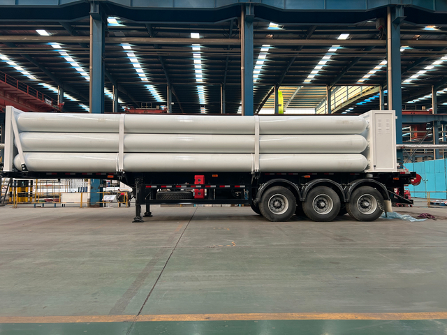
Virtual pipelines and CNG tube trailers present a specific operational challenge. The inlet pressure (P1) decays continuously as the trailer empties into the PRU. Operators must establish the minimum allowable inlet pressure required to sustain peak flow before a trailer swap is necessary. If the minimum P1 drops too close to the required outlet pressure, the regulator fails to deliver the necessary volume. For example, a system requiring 1,000 SCMH at 5 bar might easily pass that volume when the trailer is at 200 bar. However, when the trailer decays to 15 bar, the available pressure differential shrinks. The valve orifice must be large enough to pass the same 1,000 SCMH with only a 10 bar differential.
You must define the target delivery pressure to the downstream process. Applications vary wildly, from stepping down to 49 kg/cm² for intermediate distribution pipelines, to reducing pressure as low as 0.03 kg/cm² for direct feed into industrial burner tips. The PRU must maintain this setpoint accurately across the entire flow range.
Determine the acceptable variance, or droop, from the setpoint under varying load conditions. No regulator maintains a perfectly flat line; pressure inherently drops slightly as flow increases. Furthermore, you must account for downstream piping pressure drops. Using NFPA 54 guidelines, such as the Longest Pipe Run Method, ensures the PRU setpoint compensates for friction losses in the piping network before the gas reaches the end-use equipment. If the burner requires exactly 2 bar, and the 100-meter pipe run introduces a 0.3 bar friction loss at peak flow, the PRU must be set to 2.3 bar.
Quantifying flow requirements accurately is non-negotiable. Flow is typically measured in Standard Cubic Meters per Hour (SCMH) or Standard Cubic Feet per Minute (SCFM). You must standardize units carefully before beginning calculations. Converting daily metrics like 11,000 sm³/day into hourly or minute rates is mandatory for accurate Cv calculations.
A common engineering error involves sizing exclusively for peak flow, such as 6,000 SCMH, without accounting for minimum flow stability. This relationship is known as the turndown ratio. If a regulator is sized for massive peak flows, it struggles to control tiny minimum flows, leading to instability and seat damage. You must evaluate the full operational spectrum by mapping out the flow profile:
Identify the absolute minimum flow required during standby or pilot operations.
Determine the normal continuous operating flow rate.
Calculate the absolute peak transient flow during maximum equipment load.
Verify that the selected regulator's turndown ratio can accommodate the spread between step 1 and step 3.
Documenting the ambient and gas inlet temperatures is a fundamental step in the sizing process. Natural gas undergoes a significant physical change when subjected to rapid pressure reduction. This phenomenon is known as the Joule-Thomson effect.
Pressure reduction causes a predictable temperature drop. For natural gas, expect a temperature decrease of approximately 0.5°C to 0.6°C for every 1 bar of pressure drop. When dropping pressure from 250 bar down to 4 bar, the temperature plunge is severe. This thermal shift dictates material selection and necessitates external heating to prevent system failure. Ignoring this factor guarantees frozen regulators, blocked sensing lines, and ruptured downstream carbon steel pipes.
You must confirm the specific gravity of the natural gas composition being handled. Standard natural gas typically has a specific gravity of approximately 0.6 relative to air. This value directly impacts the flow coefficient calculations and density variables used in sizing formulas.
Heavier gas mixtures flow differently through an orifice than lighter gases. If the specific gravity deviates from the standard 0.6 due to high ethane or propane content, the calculated Cv must be adjusted. Ignoring specific gravity leads to inaccurate capacity predictions and potential undersizing.
Gas Type | Approximate Specific Gravity (Air = 1.0) | Impact on Flow Capacity vs. Standard Gas |
|---|---|---|
Standard Natural Gas (High Methane) | 0.60 | Baseline for standard Cv calculations. |
Rich Natural Gas (High Ethane/Propane) | 0.65 - 0.70 | Decreases actual flow capacity. Requires a slightly larger Cv. |
Biogas / Landfill Gas (High CO2) | 0.80 - 0.95 | Significantly decreases actual flow capacity. Requires a much larger Cv. |
Clarify the engineering distinction between line size and valve size. End connection sizes, ranging from 1" NB to 4" or larger, dictate how the unit integrates into the physical piping. However, the internal orifice sizing dictates the actual flow capacity. A 2" regulator does not necessarily have the same capacity as a 2" pipe.
Incorporate gas velocity (V) calculations into your design. Ensure that while the valve Cv meets flow demands, the selected line size keeps gas velocities below erosive and acoustic limits. For continuous service, gas velocity should typically remain below Mach 0.3 to 0.5. High velocities strip pipe walls, generate deafening noise, and create excessive vibration. If the calculated velocity in a 2" downstream pipe hits Mach 0.6, you must expand the downstream piping to 3" or 4" immediately after the regulator, even if the regulator itself remains a 2" body.
The Flow Coefficient (Cv) is the universal metric for comparing valve capacities. It represents the volume of water in US gallons per minute that flows through a fully open valve with a pressure drop of 1 psi. For gases, the formula incorporates specific gravity, absolute temperature, and absolute pressure differentials.
You must calculate the Cv for two distinct scenarios. First, calculate the Cv required for maximum flow at the minimum inlet pressure. This is your worst-case capacity scenario. Second, calculate the Cv for minimum flow at the maximum inlet pressure. This ensures the selected regulator throttles down effectively without losing control. Proper CNG pressure reduction unit sizing relies heavily on balancing these two extremes. If the required Cv for peak flow is 15, and the required Cv for minimum flow is 0.5, you need a regulator with a turndown ratio of at least 30:1.
Flow calculations change dramatically based on the pressure ratio across the regulator. You must determine if the flow is critical or sub-critical. Critical flow, also known as choked flow, occurs when the gas velocity reaches sonic speeds (Mach 1) at the vena contracta, the narrowest point of the valve orifice.
This happens when the absolute outlet pressure (P2) is less than half of the absolute inlet pressure (P1). Once flow becomes critical, lowering the downstream pressure further does not increase the flow rate. The sizing formula shifts to account for this choked condition, relying solely on the inlet pressure to determine maximum capacity.
Flow Condition | Pressure Ratio (P2 / P1) | Velocity at Vena Contracta | Impact on Capacity Calculation |
|---|---|---|---|
Sub-Critical Flow | Greater than ~0.5 | Sub-sonic (< Mach 1) | Flow increases as P2 decreases. Both P1 and P2 dictate the flow rate. |
Critical (Choked) Flow | Less than ~0.5 | Sonic (Mach 1) | Flow is capped. Lowering P2 further yields zero additional flow. Capacity depends only on P1. |
Basic Cv calculations provide a baseline, but manufacturer flow curves predict actual real-world performance. You must read these charts to understand how a regulator behaves across its entire stroke. A flow curve plots outlet pressure on the Y-axis against flow rate on the X-axis.
Identify droop and lock-up on these curves. Droop is the natural drop in outlet pressure as flow demand increases. Lock-up is the pressure spike that occurs when flow drops to zero and the regulator forces itself tightly closed. Selecting a regulator with a curve that stays within your acceptable pressure tolerance across your required flow range is the ultimate goal of the sizing process. If your process requires 5 bar +/- 0.2 bar, and the flow curve shows a droop down to 4.5 bar at peak flow, that specific regulator fails your application requirements.
Thermodynamics play a dominant role in high-pressure gas reduction. You must calculate the expected downstream temperature based on the maximum pressure differential. Using the standard metric of a 0.5°C to 0.6°C drop per 1 bar of reduction, a massive pressure cut yields extreme cold.
Identify the threshold where gas temperatures drop below the dew point or freezing point. Taking natural gas from 200 bar down to 10 bar results in a 190 bar drop. This translates to a temperature plunge of roughly 95°C to 114°C. If the inlet gas is at 20°C, the downstream temperature easily reaches -75°C or lower. This freezes moisture, creates hydrates, and shatters standard carbon steel piping. You must upgrade downstream piping to low-temperature carbon steel (LTCS) or stainless steel if these temperatures are expected even momentarily during startup.
To offset this severe temperature drop, you must evaluate and size heating solutions. The heater injects thermal energy into the gas stream before the pressure cut to ensure the downstream temperature remains safely above freezing, typically targeting a minimum of 5°C to 10°C.
Heater capacity, measured in kW or BTU/hr, must be sized concurrently with the PRU flow rate. If the heater is undersized relative to the gas mass flow, it creates a thermal bottleneck. The regulator might have the physical capacity to pass the gas, but the system freezes solid, forcing a complete shutdown. Follow these steps for heater integration:
Calculate the maximum mass flow rate of the gas.
Determine the total required temperature delta (Target downstream temp + Joule-Thomson drop - Minimum inlet temp).
Apply the specific heat capacity of natural gas to find the total required thermal energy in kW.
Select a heater type (Water Bath, Electric, or Catalytic) that meets this kW rating while accounting for efficiency losses.
Heater Type | Mechanism | Best Application Scenario |
|---|---|---|
Water Bath Heater | Uses a gas burner to heat a water/glycol bath, which transfers heat to gas coils. | High-flow, continuous operations like city gate stations. Requires a large footprint. |
Electric Process Heater | Direct contact electric elements heat the gas stream. | Compact skids, offshore platforms, or sites with abundant electrical power. |
Catalytic Heater | Flameless catalytic reaction generates radiant heat. | Remote, off-grid locations with low flow rates and strict hazardous area classifications. |
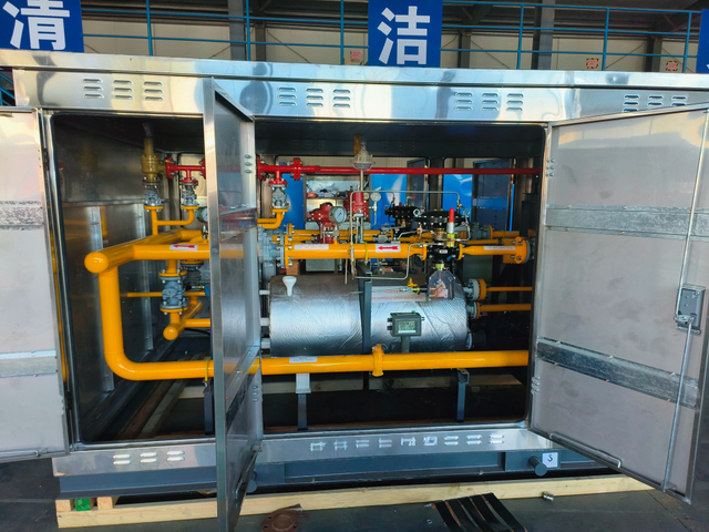
Engineers must evaluate when a single-stage cut is sufficient versus when a two-stage or three-stage reduction is required. A single-stage cut works well for moderate pressure differentials where the Joule-Thomson effect is manageable and noise limits are not exceeded.
Multi-stage reduction becomes necessary to manage extreme pressure differentials. By breaking a 200 bar drop into two 100 bar drops, you distribute the thermal load, allowing for inter-stage heating. Multi-stage setups also mitigate velocity-induced noise and prevent severe cavitation-like damage to regulator internals. A common CNG setup drops 250 bar to 40 bar in the first stage, applies inter-stage heating, and then drops 40 bar to 4 bar in the second stage.
System redundancy guarantees uptime and safety. Compare the Active and Monitor setup against a parallel twin-stream setup. An Active/Monitor configuration places two regulators in series. The active regulator does the work, while the monitor stays wide open, ready to take over instantly if the active unit fails open. You must assess the impact of series regulators on overall system Cv, as placing two valves in series reduces the total flow capacity by approximately 30%.
A parallel twin-stream setup provides 100% redundancy. Two identical PRU lines run side-by-side. One handles the full load while the other remains on standby. This allows technicians to isolate and maintain one stream without interrupting the downstream gas supply. For critical industrial processes where a gas outage costs thousands of dollars per minute, twin active streams are mandatory.
Protecting downstream piping from overpressurization is a strict requirement under NFPA 54 and ASME B31.8 standards. If a regulator fails open, high-pressure gas floods the low-pressure system, causing catastrophic ruptures. You must detail the integration of safety devices.
Slam-Shut Valves (SSV) provide the ultimate protection. They monitor downstream pressure and snap completely closed if the pressure exceeds a safe setpoint, requiring manual reset. Pressure Relief Valves (PRV) offer secondary protection by venting excess gas to the atmosphere. Environmental regulations often limit PRVs as the primary safety mechanism due to methane emission restrictions, making SSVs the preferred choice for primary overpressure protection.
Oversizing a regulator is a frequent and damaging mistake. When a valve is too large for the required flow, it operates very close to its seat. The plug barely lifts to satisfy the demand. This causes hunting, where the regulator rapidly fluctuates open and closed, trying to find a stable position.
Hunting creates severe pressure spikes and rapid mechanical wear. The constant slamming of the plug against the seat destroys the soft trim materials. An oversized regulator requires frequent maintenance, rebuilds, and ultimately premature replacement. Engineers must resist the urge to add massive safety factors to flow rates, as this directly causes oversizing.
Undersizing directly impacts process viability. Undersized units fail to meet peak demand. When the downstream equipment calls for more gas than the regulator can pass, the downstream pressure collapses.
This pressure collapse results in process starvation. Burners flame out, turbines shut down, and production halts. Undersizing often occurs when engineers calculate Cv based on normal flow rates while ignoring transient peak demands or failing to account for the lowest possible inlet pressure from a decaying tube trailer.
High-pressure, high-velocity gas expansion generates immense acoustic energy. Address the acoustic risks inherent in CNG applications. Noise levels easily exceed 110 dBA, violating occupational safety limits and causing structural fatigue in the piping through severe vibration.
Evaluate noise attenuation features required when sizing units for noise-sensitive environments. Specialized noise-abatement trims inside the regulator break the gas flow into smaller jets, shifting the noise frequency. Additionally, installing inline silencers and expanding the downstream piping diameter immediately after the regulator helps slow the gas and mitigate acoustic hazards.
Noise Attenuation Strategy | Implementation Method | Expected Noise Reduction |
|---|---|---|
Source Treatment (Whisper Trim) | Replace standard regulator cage with a drilled or slotted noise-abatement cage. | 10 to 20 dBA reduction at the valve body. |
Path Treatment (Acoustic Insulation) | Wrap the valve body and downstream piping in acoustic blankets or lagging. | 5 to 10 dBA reduction (only masks the noise, does not fix internal vibration). |
Velocity Control (Pipe Expansion) | Increase downstream pipe diameter using eccentric reducers to slow gas velocity below Mach 0.3. | Prevents secondary noise generation in the piping network. |
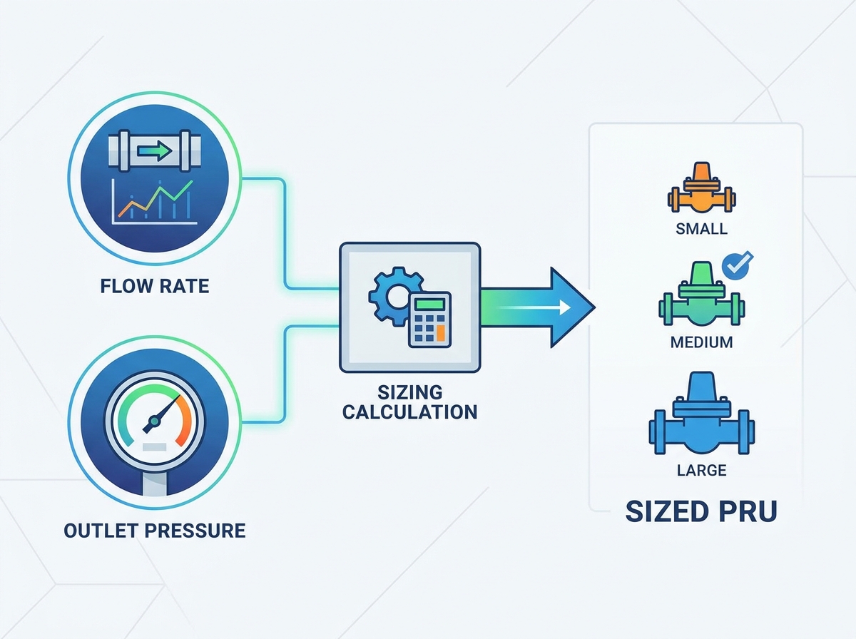
Gather the six governing application data points: P1 (min/max), P2, Flow (min/max), Temperature, Specific Gravity, and allowable Line Size.
Calculate the required heating load (kW or BTU/hr) to offset the Joule-Thomson temperature drop before finalizing the skid footprint.
Consult with a specialized gas control engineer to generate a custom sizing calculation and flow simulation to verify sub-critical or critical flow states.
Select a redundancy configuration (Active/Monitor or Twin Stream) that aligns with your facility's maintenance capabilities and uptime requirements.
Beijing SinoCleansky Technologies Corp is an experienced manufacturer of natural gas equipment, providing integrated CNG, LNG, and NGV solutions covering products, technology, and technical services. With expertise in high-pressure and cryogenic equipment and a focus on international quality standards, SinoCleansky supports customers with reliable and customized gas handling solutions for diverse industrial applications.
A: Line size refers to the physical diameter of the piping connections used to integrate the unit into the facility. Valve size refers to the internal orifice and flow capacity (Cv). A regulator often has a smaller internal valve size than the connecting pipeline, but the pipeline must be sized appropriately to keep gas velocity within safe limits.
A: As a CNG source, like a tube trailer, empties, the inlet pressure drops continuously. The regulator must be sized to deliver the maximum required flow at the absolute minimum allowable inlet pressure. If sized only for the initial high pressure, the unit starves the downstream process as the trailer depletes.
A: High-pressure gas reduction causes a rapid temperature drop, typically 0.5°C to 0.6°C per 1 bar of pressure drop. Without calculating this drop and integrating proper pre-heaters, the gas freezes, forming hydrates that block flow and damage internal valve components and downstream piping.
A: Hunting is usually caused by an oversized regulator. When the valve capacity is too large for the actual flow demand, the internal plug operates too close to the seat. It rapidly opens and closes, trying to stabilize, which causes pressure fluctuations, severe vibration, and premature wear.
A: Cv is calculated using specific formulas that incorporate the gas specific gravity, inlet temperature, maximum flow rate, and the pressure differential (P1 and P2). You must calculate the Cv for both maximum flow at minimum inlet pressure and minimum flow at maximum inlet pressure to ensure full-range stability.
A: An active/monitor setup places two regulators in series; one controls the pressure while the other stays open as a backup in case the first fails. A twin stream setup places two complete regulator lines in parallel, providing 100% redundancy so one line can be fully isolated for maintenance without stopping gas flow.